
Tower Flow Graph: Making Sense of Data and Agentic Flows

Modern data pipelines and AI agents are graphs of execution, not linear scripts. Engineers increasingly define these execution graphs in code, using Python to express branching logic and loops.
But code alone doesn’t provide visibility at runtime. Debugging often means piecing together logs of multiple apps using timestamps to understand what’s happening. Today, we’re launching the Tower Flow Graph - a visualization that shows how Tower apps execute together as a single, connected flow.
Pipelines, Agents, and Graphs
For data engineers, each step in a pipeline represents a meaningful data transformation or action, such as:
joining datasets,
adding and populating new columns,
sending emails,
or retrieving data from an external API.
For AI engineers building agents, there is typically a main app that hosts the agent. This main app calls tools to accomplish tasks such as data retrieval, web searches, or API access.
Both data and AI engineers structure their systems this way for two reasons. First, it allows them to decompose a large problem into smaller, more manageable pieces. Second, it enables reuse of software components that perform a specific task. Just like with a Lego set, engineers can assemble different pipelines or agents from a common set of building blocks.
For this reason, many data pipelines in the wild look like this:

DAGs and Orchestration
In the data engineering world, a graph like this is called a DAG (Directed Acyclical Graph), and the process of executing the steps of such a pipeline is called orchestration.
After Tower introduced orchestration of apps, users told us they wanted a way to visualize app call sequences. They wanted to understand the current state of a pipeline and estimate when it would finish.
In Tower, any app can create a run of another app and either wait for it to complete or continue execution. The calling app is referred to as the parent app, and the called app is the child app.
Python-First Orchestration and Control Flows
One of Tower’s distinguishing features is that orchestration is defined entirely in Python code, rather than in YAML files or in GUI. While YAML can seem simpler at first, it limits the ability to implement more complex logic such as loops or recursion.
Defining control flows in Python - in a dedicated orchestration app - allows users to stay fully Pythonic and benefit from the full power of a procedural language, including conditional branching, loops, and recursion.
Because Tower implements orchestration in code, it does not restrict users to directed, acyclical graphs. Instead, engineers can define Control Flows: sequences of app runs that may include cycles. For example, App A can call App B, which in turn calls App A again. This is an accepted pattern in software engineering, as long as the engineer ensures that recursion or cycles terminate correctly.
Introducing the Flow Graph
With the flexibility of Control Flows, users asked for a visualization that shows which child apps are running and when they complete. This led to the introduction of the Flow Graph - a graphical representation of an app’s control flow (more precisely, of a single app run).
Before the Flow Graph, if a run of App A created a run of App B, these runs appeared separately in the Tower UI. Users could not easily see that Run B was a child of Run A. With the Flow Graph, users can now see the entire execution graph, gaining a clear understanding of how apps connect to form a larger data pipeline.
Why This Matters for Agentic Flows
The Flow Graph is especially useful for agentic flows, where a parent agent calls tools based on:
the user prompt,
the reasoning plan generated by the language model,
and the results of previous tool calls.
In agentic flows, the final shape of the graph is not known in advance. While ETL pipelines tend to have a relatively stable structure across executions, agentic flows can vary significantly from run to run. Having a graph visualizer readily available helps AI engineers understand what their agents are doing and why.
How It Works: Technical Deep Dive
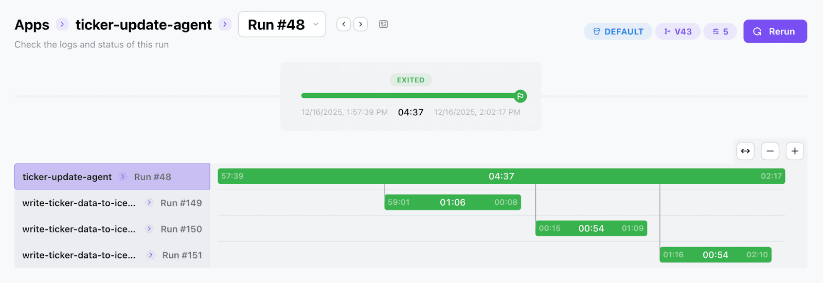
The Flow Graph is rendered as a sequence diagram. Each active app run - whether a parent or a child - is represented by a swimlane, and the X-axis represents time.
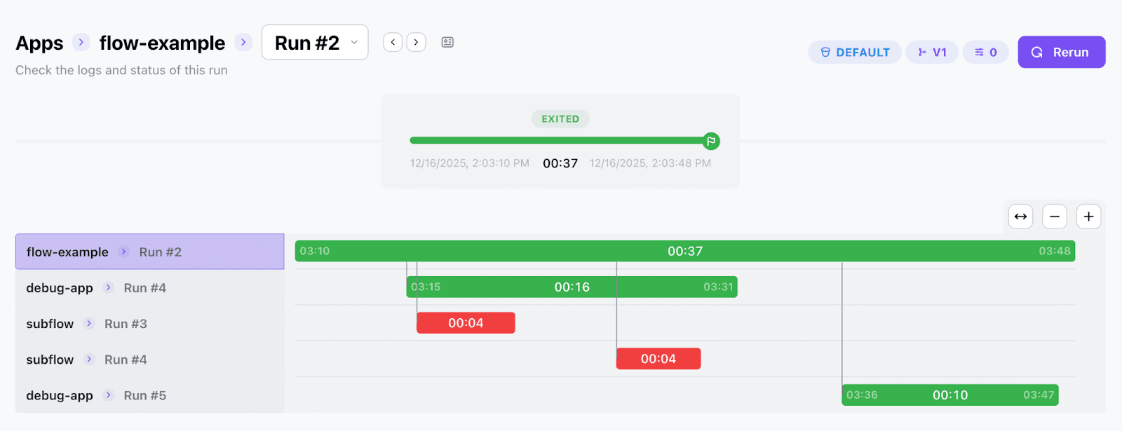
The top lane represents the parent run that initiates the flow. As the parent creates child runs, new swimlanes are added. When a child run finishes, its bar ends and control returns to the parent. This continues for as many levels of depth as the control flow requires.
When you hover over a run, you can see key metrics such as start time, end time, duration, and what initiated the run. Clicking on a bar representing a child run takes you directly to that run’s detail page.
Trying the Flow Graph
To see the Flow Graph in action, sign up for Tower and deploy some of the Tower example apps that run other apps, such as “fan-out-ticker-runs” or “ticker-update-agent”. These examples demonstrate how parent apps can trigger multiple child runs, including external API calls, within a single control flow.
Important: Make sure the Tower CLI version you use is 0.3.36 or higher when deploying these apps.
With the Flow Graph, Tower makes complex data and agentic flows visible, understandable, and easier to build with confidence.